Fun with an ESP32, Rust, and controlling a Scope with a foot pedal
I bought a very discounted ESP32 board (EPD75 originally designed as an e-paper doorbell) and have been playing with it. I've built a foot pedal set from scrap parts, and wired it, via USB to my Linux PC and used it to control my Oscilloscope, and also been able to control the nice LEDs on it from Linux. I've used the Rust language to program the ESP32. The esp rust build and configuration is mainly based around esp-hal.
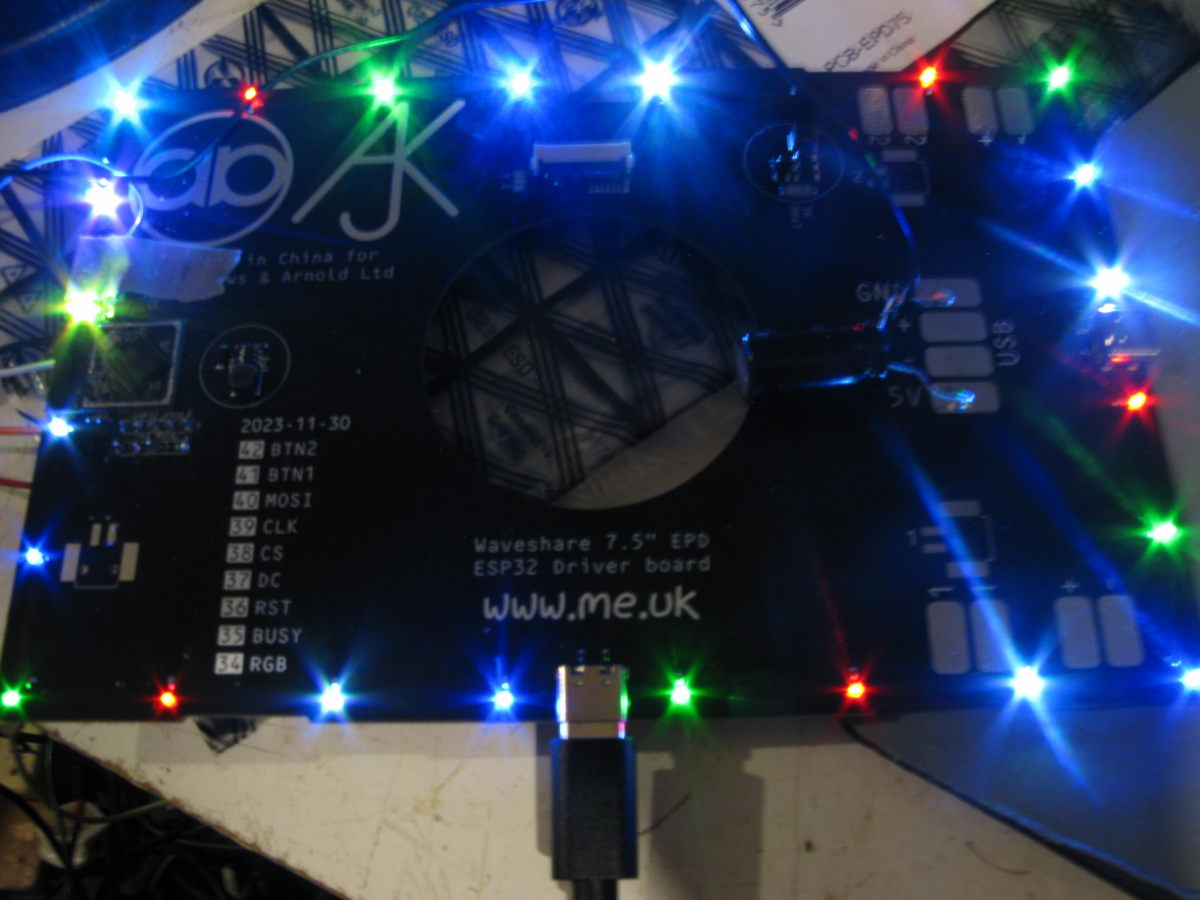
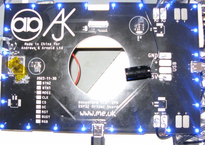 The board has a ring of programmable RGB LEDs (connected in a single chain) around the edge, two button inputs and a connector for the e-paper display (which I've not got). A pair of USB-C connectors provide host connectivity and power. I added a random fat capacitor to get it happy during programming.
- Programming
- Foot pedal
- USB and HID
- The Scope
- LEDs
Programming
Since I already knew some Rust, I decided to play with the Rust HAL on the ESP32. The flow is to install a cross compiler (for the ESP's main xtensa cores), use cargo to build Rust as normal, and then to take the generated binary and flash that image using esptool or espflash. The HAL provides reasonable abstractions for most of the hardware blocks, and then you can pull in other Rust crates as needed. At the time of writing (2026), the HAL is reasonable but still has some rough corners. The flashing tools also let you take an initial copy of the existing firmware, just in case.
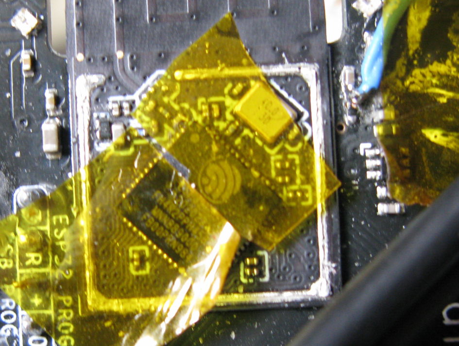
Flashing on ESP is normally done via a USB-JTAG over the normal USB connection, which is fine until you screw up the firmware (which I found out the hard way). To recover, you can force a boot into download by holding reset while also pulling GPIO0 low; this is painful especially since on my board that wasn't pinned out (although it looks like it was the intent). Which led me to taking the case of and getting to GPIO0 (pin 5 on the s3 chip itself) the hard way:
Because that's painful, I built the code around a mainloop that polls devices, including the serial port and added a simple serial port command to force it into download mode by doing:
        peripherals::LPWR::regs().option1().modify(|_, w| {
            w.force_download_boot().set_bit()
        });
        software_reset();
As long as you can get that far, then the same tools will allow programming over the simple serial interface.
My hacky code is here, I'll describe some more parts below. The initial starting point was created with esp-generate.
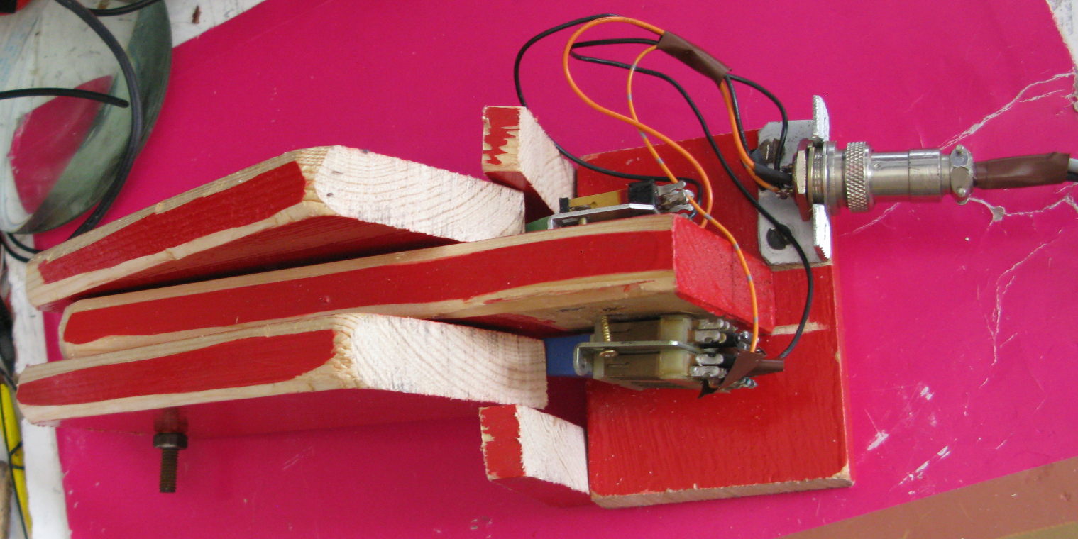
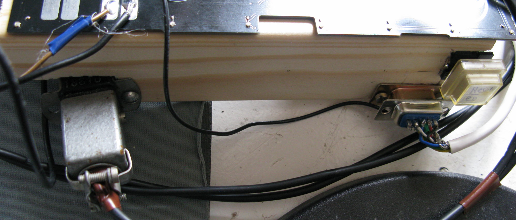
The foot pedal (pair) is entirely scrap made; a couple of old telco switches are wired to a GX20 connector, these go to the button pads (marked '1' and '2') on the board via a Jones connector at the other end;
 The crude switch generates a fair amount of bounce, this is removed in software by not sending transitions for the same switch within 5ms of the last transition.
Declaring and reading the buttons is easy enough from esp-hal (note the pull up!):
    let button1 = Input::new(peri.GPIO41, InputConfig::default().with_pull(Pull::Up));
    let button2 = Input::new(peri.GPIO42, InputConfig::default().with_pull(Pull::Up));
...
    let mut button_val = [false;2];

    button_val[0] = button1.is_low();
    button_val[1] = button2.is_low();
USB and HID
It's easy enough to instantiate the ESP's onboard USB, but note that doing so disabled the USB-Jtag easy programming system - which was the point I found out the hard way I need the GPIO0 recovery above.
The question then is what type of device to expose to the host, a USB-HID device is the obvious choice since this includes keyboard and mice and similar things. The usbd_hid Rust crate provides the basic framework for a USB-HID device, and is designed to work with a variety of different microcontrollers. This leads to the initialisation like so:
    // USB device interface - note including this will by default turn off the USB serial-jtag
    let usb = Usb::new(peri.USB0, peri.GPIO20, peri.GPIO19);
    let usb_bus = UsbBus::new(usb, unsafe { &mut *addr_of_mut!(EP_MEMORY) });

    // Device 0xffff is for dev
    let mut hid = HIDClass::new(&usb_bus, KeyboardReport::desc(), 60);
    let mut usb_dev = UsbDeviceBuilder::new(&usb_bus, UsbVidPid(0xffff, 0x0001))
        .build();
Note: I found that usbd-hid increased the image size a lot, I had to decrease the 'debug = 2' that esp defaulted to, to 'debug =1' in the Cargo.toml to get it to fit.
On a Linux host system, this appears as a new input device. HID devices work by sending reports, a Keyboard input report is sent by the keyboard to the host whenever a key transitions. The report contains (along with some flags for modifiers like shift) upto 6 key codes to indicate that those keys are currently pressed. When a key is no longer pressed that's indicated to the host just by sending a report without that key being included in the list.
The question now is which key codes to use for the two pedals; I initially started by using 'a' and 'b' for debug, and then tried using F23 and F24 which are included in the USB definition, but didn't work well in practice under Mint on Linux; the F23 ended up resolving to disable touchpad and F24 wasn't recognised. Having tried a few, I settled on 'Keypad Equals' and 'Execute' (which shows up on Linux as Open), these were then easy enough to bind to custom global shortcuts in the window manager:
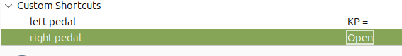
I bound those to run the shell scripts left-green-pedal and right-blue-pedal and fill those in later.
HID also supports output reports, which while partially defined in HID, can be abused fairly easily to send arbitrary data from
the host to the device. By default a single byte report is used to set keyboard LEDs, I bound a 2 byte report to let me change the key codes
sent on the fly:
    match hid.pull_raw_output(&mut raw_buf) {
        Ok(len) => {
            match len {
                2=> {
                    key_codes[0]=raw_buf[0];
                    key_codes[1]=raw_buf[1];
                },
I explain how to send output reports from Linux below in the LED section.
The scope
My scope is a Rigol DS1102Z and it's got an ethernet connection and has the hostname 'ronnie'. With foot pedals that lets me control the scope while I'm holding a probe on a test
point. From shell script, the lxi command (in the lxi-tools package) which can take screenshots and issue SCPI commands to control the scope.
For the left pedal I used the simple script:
FILENAME=$(date "+scope-%Y-%m-%d-%H_%M_%S.bmp")
# on my scope, with the current plugin this gives a bmp

lxi screenshot -p rigol-2000 -a ronnie $FILENAME
xdg-open $FILENAME
Which lets me take a screenshot from the scope. Note whether you get a bmp or png depends on the mood of lxi and your scopes firmware. For my Rigol its network connection is a bit slow so this does take a few seconds.
For the right pedal my script makes it cycle through different modes, between stop, single trigger and continuous sweep,
SCOPE=ronnie

CURRENT=$(lxi scpi -a $SCOPE ":TRIG:STAT?")

case $CURRENT in
  AUTO)
    lxi scpi -a $SCOPE :STOP
    ;;

  STOP)
    lxi scpi -a $SCOPE :SINGLE
    ;;

  WAIT)
    lxi scpi -a $SCOPE ":TRIG:SWEEP AUTO"
    lxi scpi -a $SCOPE :RUN
    ;;
esac
LEDs
The board has a set of 24 RGB LEDs with integrated controller. These are wired as a daisy chain; the protocol on these is very crude and timing sensitive. Fortunately the esp_hal_smartled crate already does the hard work by misusing the ESP's remote control transmitter (rmt).
    let led_rmt = Rmt::new(peri.RMT, Rate::from_mhz(80)).expect("Failed to initialize RMT for LED");
    let mut leds_rmt_buffer = smart_led_buffer!(NUM_LEDS);
    let mut smart_leds = SmartLedsAdapter::new(led_rmt.channel0, peri.GPIO34, &mut leds_rmt_buffer);
    let mut led_state = [colours::BLUE; NUM_LEDS];
Note that there's some oddity with the types at some point being converted to RGB and Rust sometimes does that automatically, and sometimes doesn't.
 The LEDs are very very bright, taking them down to their lowest setting makes them pleasant rather than blinding.
Controlling these LEDs is done from a 4 byte output report, specifying LED number and then the RGB values; alas, there seems to be no standard for
how to control RGB LEDs over USB. To send an output report from Linux echo'ing into /dev/hidraw1 (or whatever number corresponds to your device)
works, e.g.
echo -n '\0\001\777\777\777' > /dev/hidraw1
will send a 4 byte output report (the leading \0 is a dummy) setting LED 1 to full 255 brightness (i.e. octal 777).
TODO - 2026/03
I think that's basically all I'm going to do for now, some things I could try:
- Use the bluetooth to accept a remote keyfob input or trigger a remote capture on a phone
mail: fromwebpage@treblig.org irc: penguin42 on libera.chat | matrix: penguin42 on matrix.org | mastodon: penguin42 on mastodon.org.uk
back
to Dave Gilbert's Home Page