Epson HX-20 laptop
A friend gave me a spare Epson HX-20 (he had two!) which was partially working. I've got it happier, and describe getting a few things going.
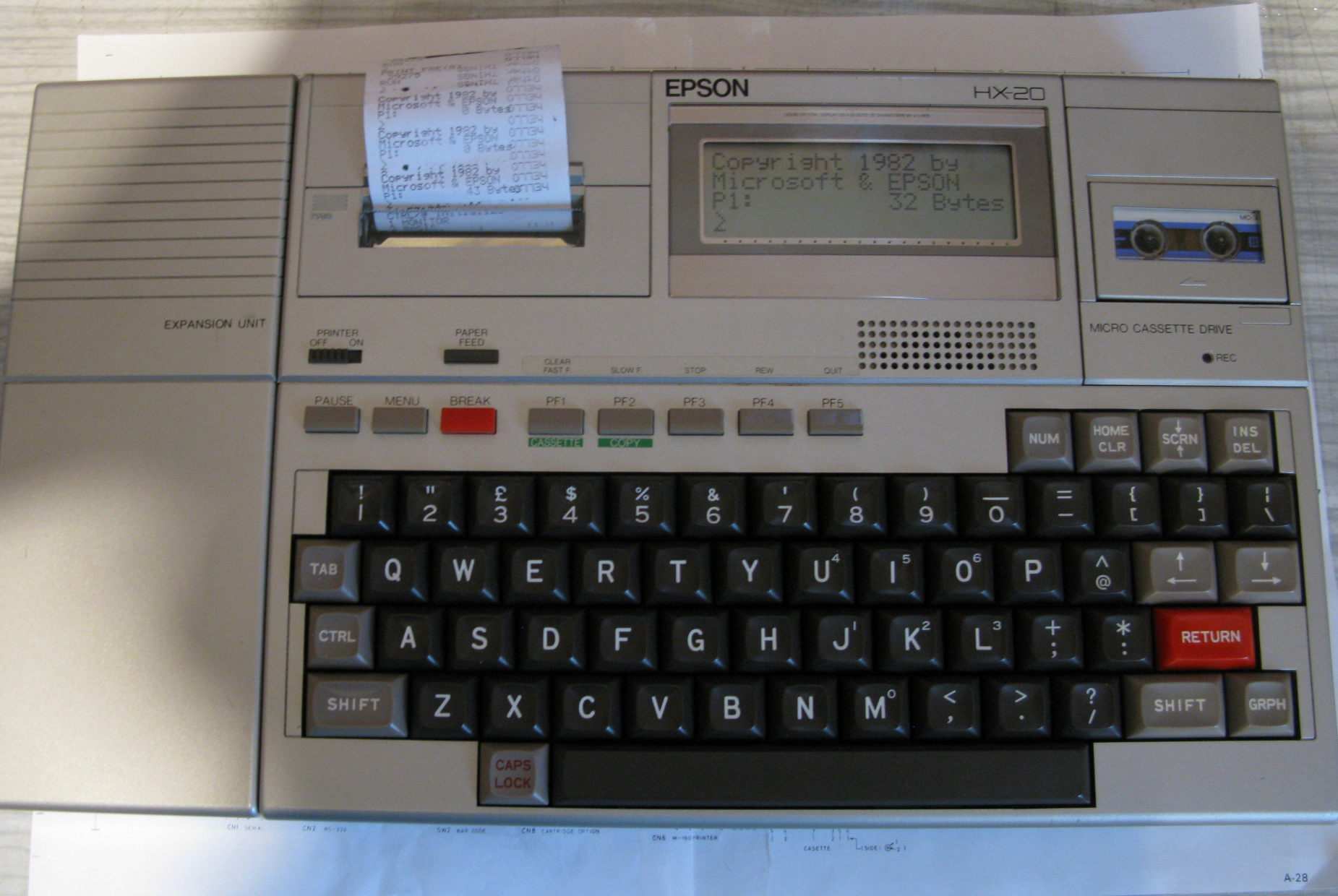 The Epson HX-20 is a very early laptop from about 1982. It's got a pair of H63C01 CPUs running at 614kHz, a microcassette drive (which can be swapped for a ROM cartridge), a printer, and a built in 4 line graphics LCD, and 16kB of RAM. Mine comes with the expansion unit which gives it an extra 16kB of RAM. It's got an internal OS in ROM and a pretty good BASIC in ROM as well. There's space internally for an extra ROM and the expansion unit has room for two more.
One nice feature is that it could run for quite a while off internal NiCD batteries, and they would preserve the RAM while it was off; together with the OS in ROM, it meant it was ready to use instantly.
In some ways, it's as much an exhibition of Epson's capabilities with the tiny printer, they sell similar ones for tills, the LCD and the microcassette.
A good stash of documents is on Phil's page. The documentation is excellent,
although the Tech reference manual doesn't always agree with the main schematic, which in general is correct.
- Fixing the hardware
- The Tape
- Intext
- TODO
Fixing the hardware
As I received it, it was clean and basically worked. The NiCD's had been removed and a power lead bodged on the NiCD connector. It ran on 6v
but the LCD was faint, and I had problems with stability and with the RS232 port. Also, it really shouldn't need 6v, the NiCD was supposed to be 4.8v
max, with a 4.5v low voltage cutoff.
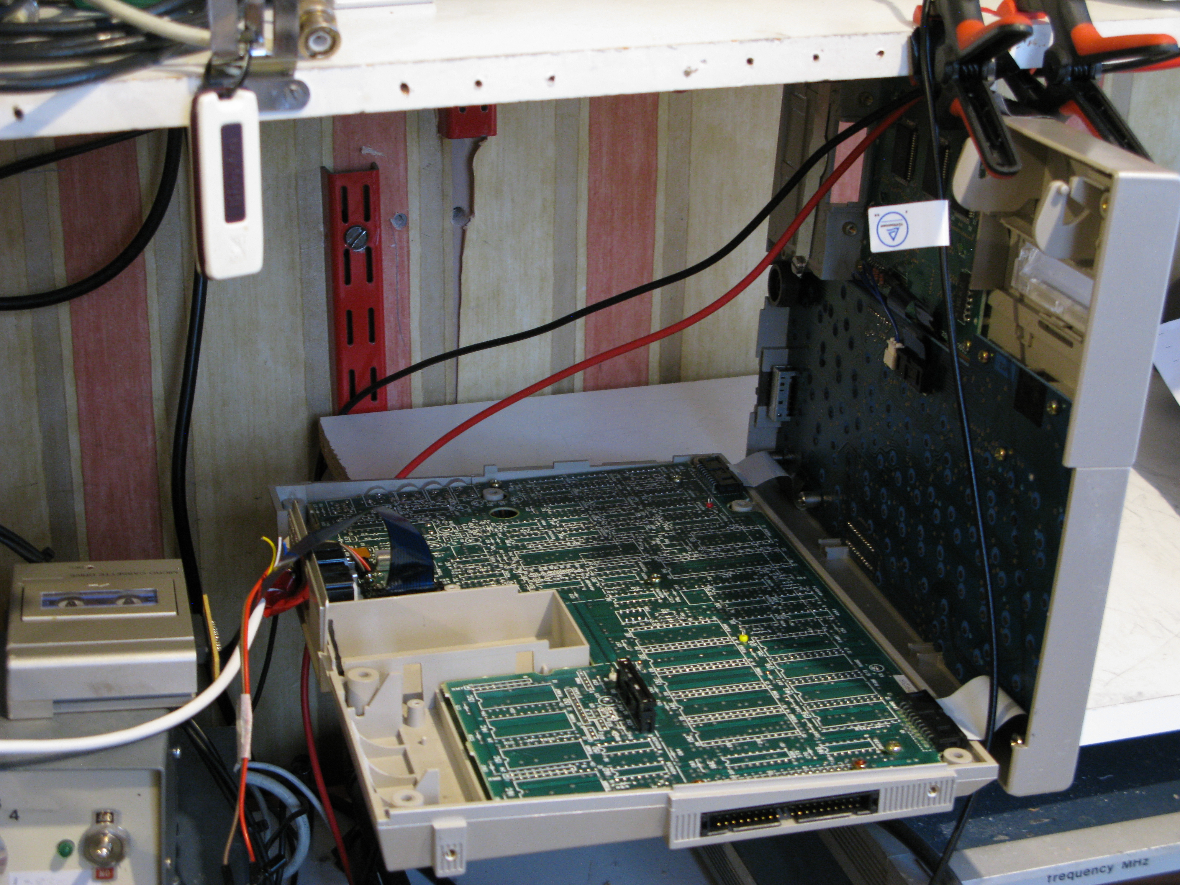
It's pretty easy to work on, the two halves of the case fold out (after unplugging a couple of ribbon cables) and the main board is a simple two sided PCB with through-hole components. The back of the main board is very well labelled, so finding pins to check is easy. One constraint is that there's not much height, so they used pretty flat components. After some basic checks I started digging further.
LCD caps
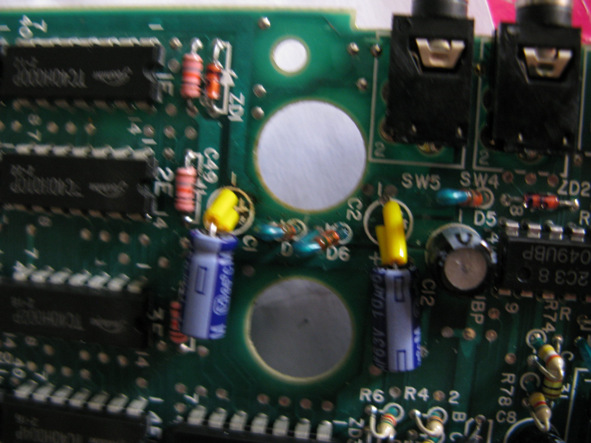
The Epson uses a very crude DC-DC converter to boost the battery voltage for the LCD - the hardware manual claims this should be a smooth ~7v. Looking on a scope, I was seeing it pretty much following the battery voltage and in no way being smooth. The DC-DC is actually just a hex inverter chip wired as a crude oscillator followed by 4 in parallel as a driver, followed by a diode and a bunch of caps. Looking closely at those caps, C6, a 10uF electrolytic, looked like it had leaked. Replacing C1, C2, C6 - all 10uF around the LCD circuit (although some at other places on the board). The capacitors I had were a bit tall to fit, so I put them on their side; there is generally enough space to squeeze stuff in:
 With those capacitors replaced, the LCD was now working OK down to 5v battery input, and the system itself was stable down to about 5.5v input.
RS-232
On the back is an RS-232 port on a DIN plug. This should not be confused with the 'serial' DIN on the back, which is for expansions and connecting HX-20's together. I bodged together a serial cable to my PC (more below) but found that when ever I tried to use the 232 I got a 'charge battery!' message and the HX-20 wanted to shut down. It needed about 6.1v input to stop that happening. The 232 has another (slightly-less-)crude DC-DC to generate +/- 8v, it's only switched on when the 232 code is running. Replacing a bunch more of capacitors made no difference to the 232 (although the stability of the system was starting to get better at lower voltages); and that was true until I replaced the C13 100uF near the printer, that helped a lot and the 232 was OK down to 5.5v input. Not all replaced capacitors were bad, on testing some were still low ESR and about correct capacitance.
One mistake I made was concentrating too much on short spikes on the power caused by the DC-DC from the 232. Setting a trigger on the 4.5v (which is what triggers the 'charge battery') and zooming in on the spikes initially got me hideous output like:

The ~40kHz repetition is the frequency of the DC-DC, and we can see a truly horrid drop to under 3V and a peak of 6.52v (higher than the input supply). While this is awful, it hides a deeper problem which is only seen on a slower timebase (albeit taken closer to the DC-DC than the last one):
 That slow drop off made me realise the problem was not a high frequency issue; tracing that back led me to the bodged battery in connector which was high resistence, but didn't really cause a problem until the higher current load when the 232 was operating. Replacing the battery lead got me the, slightly more sensible:
 While this is still very spikey, it's worth noting it's on the Q2 transistor right next to the DC-DC. I finally added an extra 1uF capacitor between R2 and the nearest ground I could find (which is still a little bit far away).
With all these fixes, I could run some basic 232 testing right down to 4.9v input.
Batteries - or lack there-of
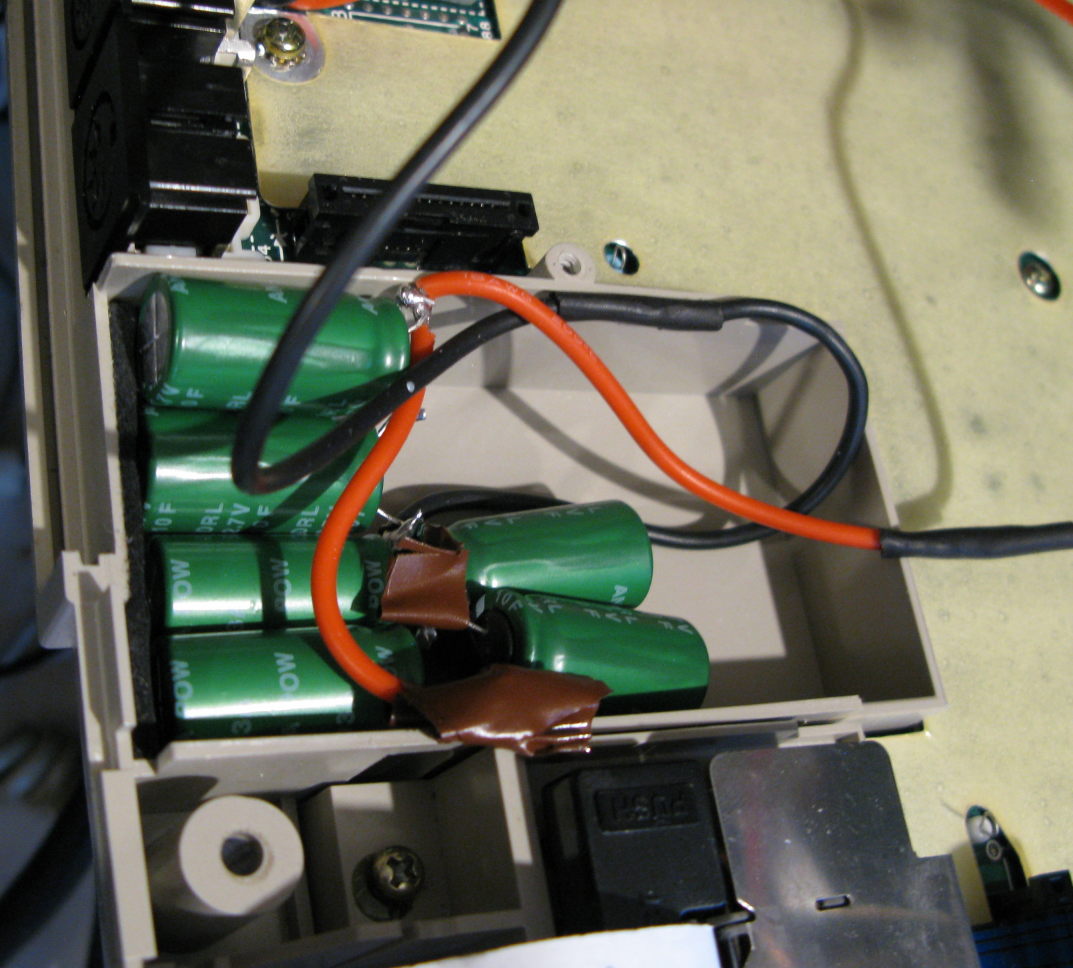
The original NiCd pack was long gone, and at this point I was running on power bodged into the battery input connection. While functional, it lost two main advantages of the Epson, running for a long time off battery, and the instant-on. The charger circuit in the Epson is very basic - just a diode and resistor, and so adding a modern Li battery felt dodgy. I took a simpler step of adding a set of super-capacitors, 6x(10Fx2.7v) wired as 30F x 5.4v. These fit with plenty of space to spare in the existing battery box. These run for 10s of minutes mostly idle, and retain memory for many hours (over night on a good day, maybe less with the expansion unit). So while it doesn't let it usefully run on battery, it does mean that you can set it up and come back without having to reconfigure everything, and it will hold the contents while you move input power. It might be possible to use 25F or larger capacitors.
Now that I was running with the capacitors in the battery box, I was supplying power via the original input socket. I noticed that the diode D2 (a S5277B), has a drop of about 0.7v, I replaced this with a 11DQ10 whose drop is closer to about 0.5v. This lets me keep the capacitors full at about 5.8v input, and even 5v input would be useful to keep memory contents. Note: It's not safe to remove the diode, it's not only for reverse input protection, it also stops the batteries feeding back to the power input.
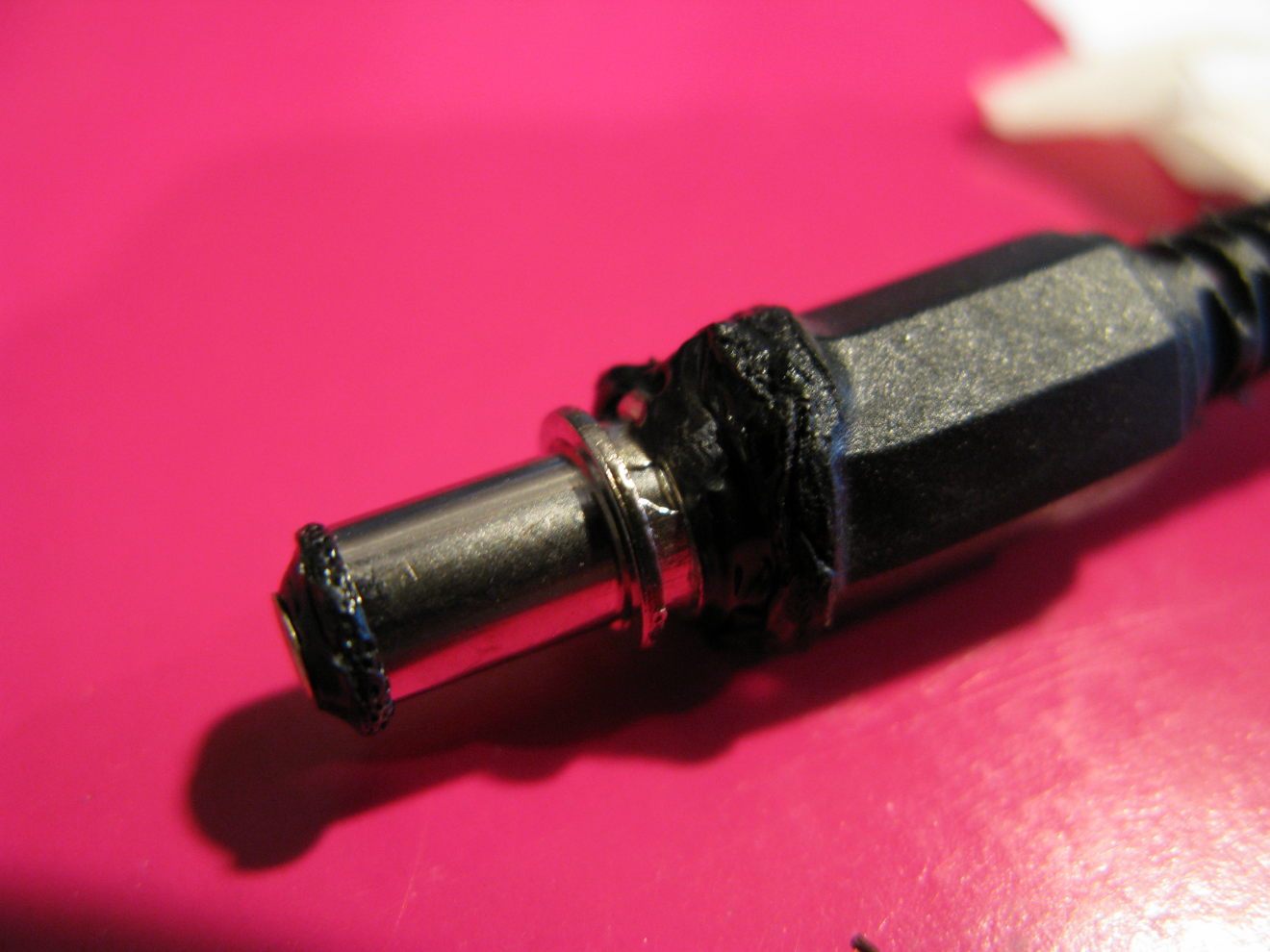
Power plug - warning
Note that the outer connector of the power jack is +ve, which is a very rare configuration these days, not least because if you were to accidentally put it down it would short, ahem:
Status
It's now pretty usable, although I do see the occasional crash. When running the cassette for a long time (many minutes), even on power, it can get upset, so I stop it regularly.
The Tape
The Epson came with a microcassette in its drive. It seemed appropriate to find out if there was anything on it.
Using the FILES "CAS0:" command I could list the files on the tape. There was a trivial little diary program on one side, but a few copies of a BASIC program called Till on the other. One of those IO errored, but another loaded fine. By Peeking &H348..34D I was able to get the date as 4th August 1984!
Examining the listing it's a simple till program for a Garden centre in St.Albans, listing items such as Shrubs, Conifers, Bedding Plants etc. I captured the listing over 232 to Minicom on a Linux PC by using the command:
SAVE"COM0:(68N1F)",A
Which is 4800bps, 8bit, no parity, 1 bit stop, no hardware flow control, with a A for ASCII.
Intext
At start up, after a hard reset, the Epson started up with Intext as an option in its main menu after the Monitor and BASIC. This was coming from an EPROM installed in the Expansion unit:
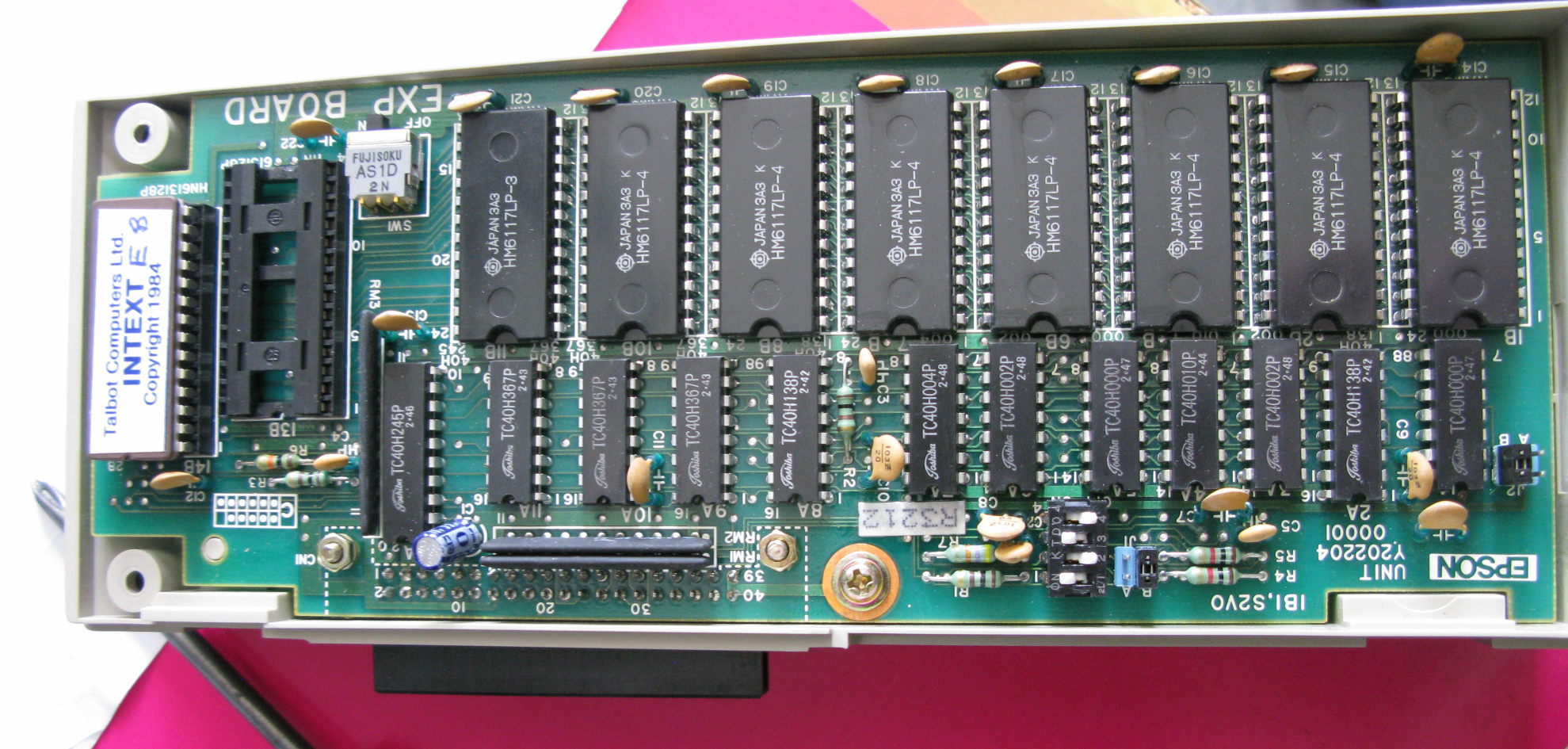
(A fun aside is that the RAM chips in the expansion are 6117 rather than the more common 6116. They have a lower power mode where they disconnect from the bus more to save power, this does lead to them having slightly different enable signals).
Intext is a very simple word processor and comms package. One of it's uses was for journalists to enter a story on the road and upload it (over an acoustic coupler). It has the ability to embed simple formatting controls, but isn't WYSIWYG on the display. The manual explains that they've agreed the code with the Journalist and typographical unions!
Selecting Intext gave an error about not having enough memory though and to look at the manual. Alas the only manual I could find was for the Cassette version which didn't mention the error.
My friend had assumed that this was a RAM fault, but PRINT FRE(0) from BASIC showed the magic 29275 bytes free that everyone was expecting there to be with the expansion unit. I later confirmed that I could read and write the expansion unit RAM by using the 'S' command in the monitor.
Getting to the Intext EPROM
To try and debug this I decided to dump the Intext EPROM. I don't have any other suitable hardware currently running, and given the EPROM is happily sat in the expansion unit, it seemed best to do it in situ. The tricky problem is that it is a banked ROM, only accessible when the BASIC ROM is paged out, and thus I couldn't access it using PEEK from BASIC.
Entering the monitor normally shows the BASIC ROM paged in, at one - non repeatable - point I managed to get Intext to trap as it printed its error out, and that landed in the monitor, and I could see the INTEXT header around 8000. Alas that was not repeatable. I eventually managed it by running the BASIC commands:
POKE &H7E,&H80
POKE &H30,&H30
The first of those enables poking at IO space from BASIC, the second changes the paging bit, paging out BASIC, and paging INTEXT. Unsurprisingly BASIC isn't too happy to be paged out, and traps - landing in the monitor, with INTEXT paged in.
It's easy to show the memory from the monitor using D 8000 and I also verified that it seemd to be 8kB, not 16kB. The monitor offers the 'W' command to write out an area of memory, alas this only allows writing to the internal or external cassette, and not to serial. Based on the documentation in the Operations manual chapter 9, I came up with the magic:
A
  T 8000
  L A000
  O 0
  E 0
WC,INTEXT.BIN
Which dumps from 8000..A000 to the external cassette with the given filename. (I think L should actually be 9FFF since my file was one byte too long).
Audio to file
Using a jack lead, I connected the Epson to the audio in on my PC, oddly this seems to be the 'MIC' connector on the Epson. Note that the connector is
deeply recessed, so you'll need to find or forcibly modify a jack lead to fit. I used a shorter dump to let me adjust the volume so that it was showing
high but not full volume on the mixer, and then used the Linux command:
parecord -r --channels=1 epson.raw --file-format=raw --format=u8
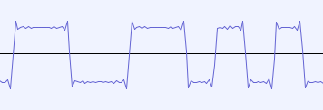
to record the audio as an unsigned 8 bit, mono, raw file; for me this came out at 44.1kHz. The Epson audio output is a surprisingly crude square wave,
with 0 and 1 represented by either a 1kHz or 2kHz cycle:
Decoding the audio
I decided to write my own demodulator, although there is an existing HXTape which may be worth a try first.
My Rust based demodulator is Here as a tar and on Gitlab. It is a pipeline which works upwards, starting at samples, transitions, bits, blocks, bytes and finally files. It writes the files locally as it extracts them. This was all fairly simple, since the square wave input was easy to work with, and the entire format is documented in the manuals
Looking at the output file showed the INTEXT header near the beginning. But the file was 8960 bytes rather than the 8192 I had expected.
After some time I realised that this was because the file was in SAVEM format, and had to write another level of decoding. Thus that repo also includes desavem to extract the contents. This left me with an 8193 byte file - I think the extra byte is because the 'L' of the monitor command should be one byte before the end.
Note that neither of my programs checks the CRC or checksums.
Disassembling and understanding
To disassemble and understand the dumped machine code I used Ghidra. The current version doesn't have the Epson's 6301 in it, however there is a pending merge request. I fetched that by:
git clone https://github.com/NationalSecurityAgency/ghidra.git
git fetch origin pull/6314/head:h6031
and then copied the files from 'Ghidra/Processors/MC6800/data/languages/*6303*' into an existing, prebuilt Ghidra installation. I had to run 'ant' in the in the 'data' directory for it to use the new processor definition.
I could easily see the expected entry header, that I'd also seen in the Epson's Monitor:
            8000 ba              ??         BAh
            8001 41              ??         41h    A
            8002 ff              ??         FFh
            8003 ff              ??         FFh
            8004 80 0d           addr       entry
            8006 49 4e 54        ds         "INTEXT"
                 45 58 54
that indicates the entry is at 800d.
I could also see the error text I was trying to understand:
str_memtoosmall
        80d7 4d 65 6d        ds         "Memory too small.   See Manual.\f"
             6f 72 79
             20 74 6f
As I was going along I'd add labels for things I spotted. The start of the code had:
       entry
            800d 96 78           LDA        A,INIFLA_0078
            800f 84 80           AND        A,#0x80
            8011 27 47           BEQ        print_notenoughmem
That 78 is labelled in the Epson docs as 'INIFLA' and it tells you if BASIC has initialised. The function it
was branching to, I could see referenced the error message above and following it through I could see it
printed it and then waited for a key to go back to the menu, so labelled it 'print_notenoughmem'.
OK, so the first thing then is to make sure I start BASIC before I try starting INTEXT. Doesn't help, OK, digging further
I see that Ghidra is showing a separate piece of code that ends up at the 'print_notenoughmem' routine:
            8047 fc 01 34        LDD        BSWTAD_0134
            804a c3 00 06        ADD        D,#0x6
            804d fd 7f 58        STD        DAT_7f58
            8050 fe 7f 58        LDX        DAT_7f58
            8053 ee 02           LDX        0x2, IX
            8055 8c 02 00        CPX        #0x200
            8058 2e 0c           BGT        LAB_8066
print_notenoughmem
Ghidra reconstructed this as:
        _DAT_7f58 = (short *)(BSWTAD_0134 + 6);
        sVar1 = *(short *)(BSWTAD_0134 + 8);
        if (sVar1 != 0x200 && sVar1 + -0x200 < 0 != (SBORROW2(sVar1,0x200) != false))
        goto print_notenoughmem;
Using the Software Reference manual, I get that BSWTAD is the 'start of the BASIC application area' and the value 8 bytes in from that is 'RAM file area size'.
A working INTEXT
The BASIC reference manual showed me the second parameter of the CLEAR command sets the RAM file area size, and checking with the manual for the cassette version of INTEXT, it told you to use that to increase the size if you ran out of space. So, to get things to work:
- Initialise with Ctrl-@
- Select BASIC
- use CLEAR 50,10000 to allocate a chunk of RAM file area.
- Use the Menu button and enter INTEXT
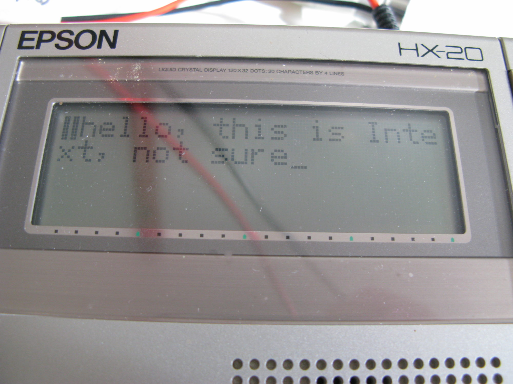
Wahey - the main INTEXT menu:
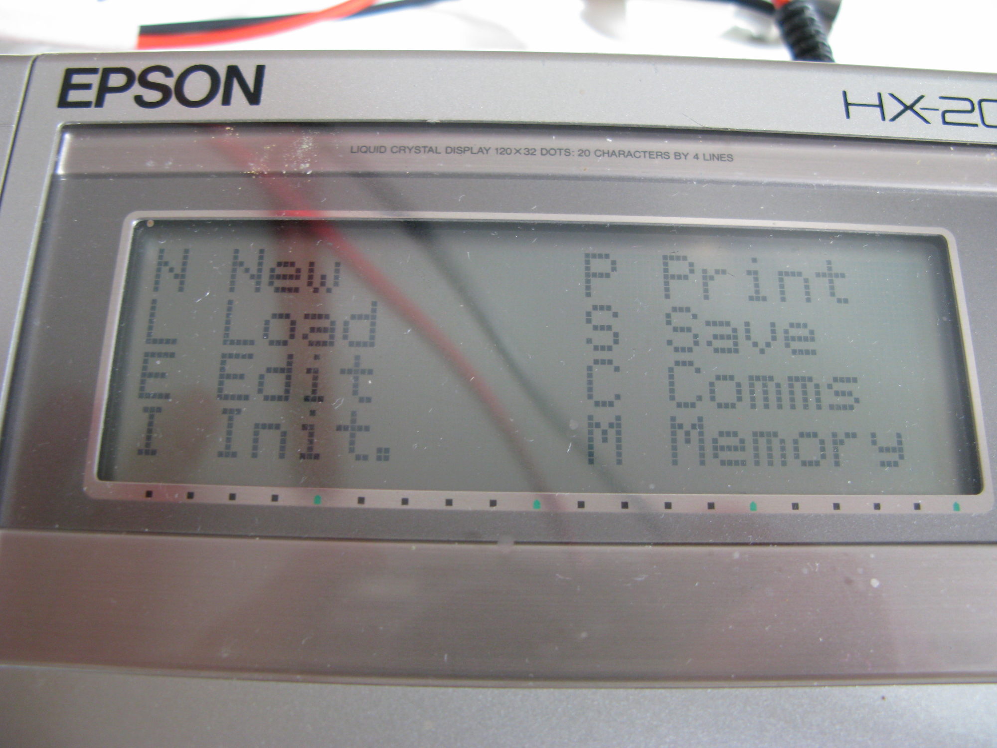 In all its glory, the INTEXT text editor:
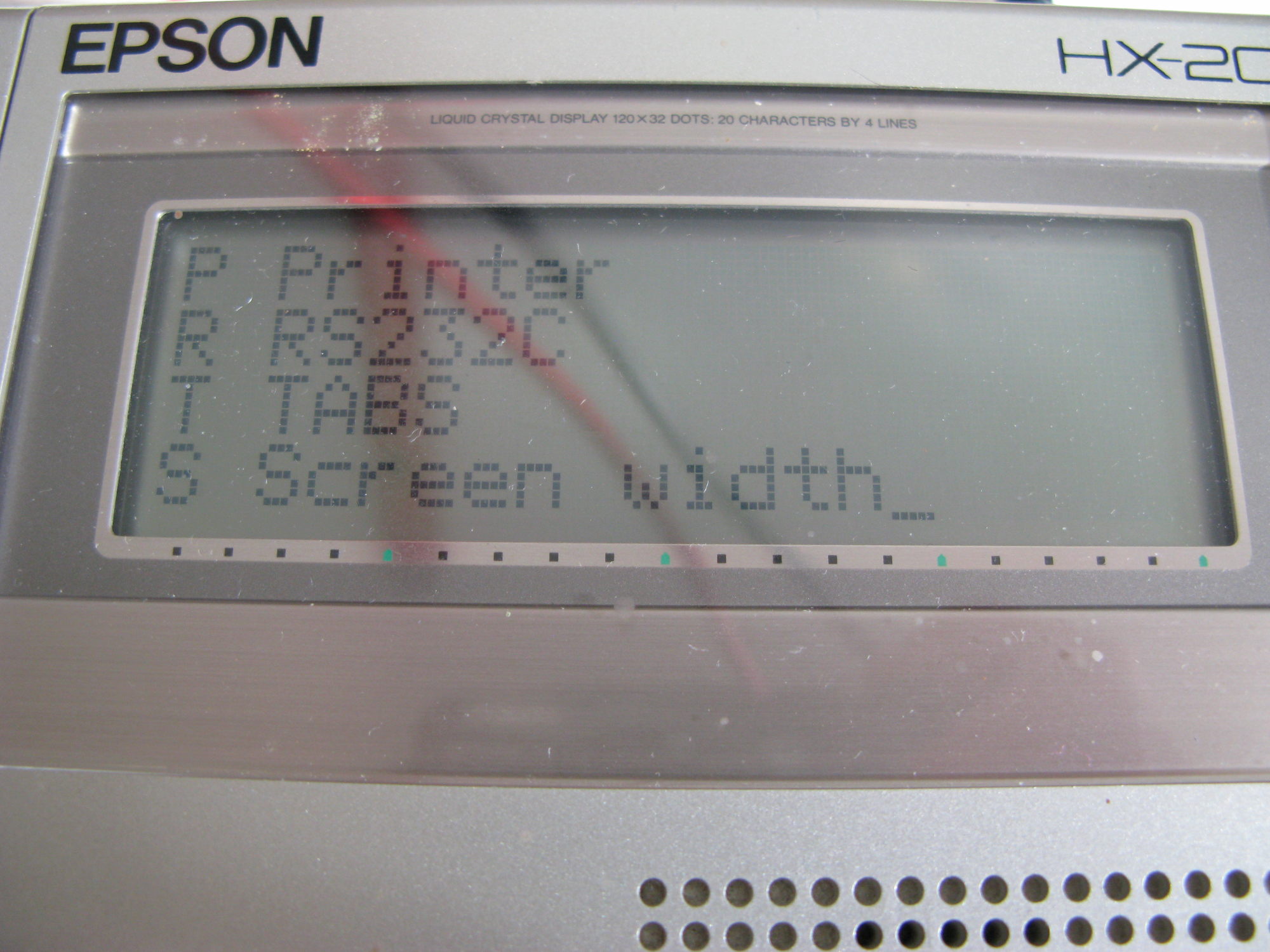
 The 'init' menu can be used to get to the RS232 options:
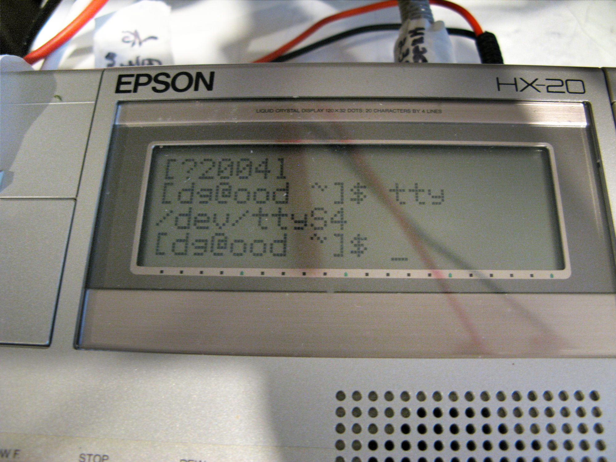
 and selecting 'Comms' from the main menu gets a simple terminal:
TODO - 2025/10
I think that's basically all I'm going to do for now, some things I could try:
- Play more with a replacement battery setup.
- Wire up a floppy emulator to the Serial (not RS232) connection
- Set up printing to it's printer or access to it's tape over the RS232 connection.
mail: fromwebpage@treblig.org irc: penguin42 on libera.chat | matrix: penguin42 on matrix.org | mastodon: penguin42 on mastodon.org.uk
back
to Dave Gilbert's Home Page